
 Deutsch
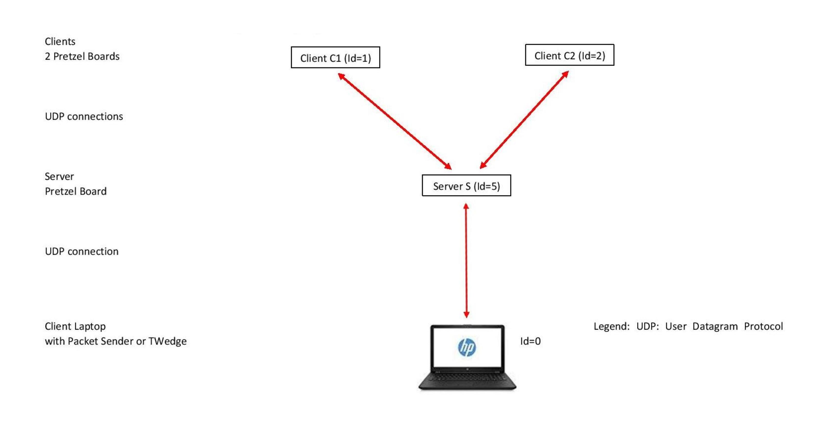
WiFi UDP Y-Network consisting of three NanoESP (Pretzel Boards) and Laptop
Download: Ernteroboter_Programme
We have designed a computer network consisting of one Server (NanoESP S), two Arduino Clients (NanoESP C1 and C2) and a Laptop as third Client (running there either Packet Sender https://packetsender.com/download or TWedge of TEC-IT https://www.tec-it.com/de/download/Default.aspx ), to construct a small UDP WiFi network. We denote it as Y-configuration, which symbolizes the connections. The center is the Server S, at the ends of the inclined arms of the Y are the Arduino Clients C1 and C2 and the vertical line is the connection to the Laptop as third Client.
The Setup
The NanoESP or Pretzel Board is a combination of an Arduino Nano and the WiFi module ESP8266, which are connected via Softserial pin 11 (Arduinos RX) and pin 12 (Arduinos TX). A similar configuration can be realized also self-made. The Clients can principally not communicate with each other directly. This can only be done via the Server. A special message structure enables this. The following IP addresses are assigned:
- 192.168.4.1 Server S
- 192.168.4.2 Client Packet Sender or TWedge:
- 192.168.4.3 Client C1
- 192.168.4.4 Client C2
Packet Sender is a program, which enables to send and to receive messsages. TWedge sends and receives messages as well, but enables to visualize the results in Microsoft Excel.
The following Ids are assigned:
- Id = 0 Client Packet Sender orTWedge
- Id = 1 Client C1
- Id = 2 Client C2
- Id = 5 Server S
The following ports are used:
- 90, 91 Client Packet Sender oder TWedge:
- 92, 93 Client C1
- 94, 95 Client C2
The sketches have the following names: S<reverse date>_<designation> with the following designations:
- UDPBidirectional-Server NanoESP S
- UDPBidirectional-Client1 NanoESP C1
- UDPBidirectional-Client2 NanoESP C2
Download: Ernteroboter_Programme
The use of library functions is omitted to have a clear idea, which AT commands are sent, to which one can refer by https://room-15.github.io/blog/2015/03/26/esp8266-at-command-reference/..A drawback of the ESP8266 is, that receivings from it can be either messages from outside or answers of the module itself (self generated answers). Sending messages via the ESP8266 is also realized with AT commands. There is no clear separation between an AT mode and working mode (sending and receiving).
All configuring AT commands are given in the Setup part of the sketch, although it would not be necessary to configure the ESP8266 after each restart. The AT commands are sent in the subroutine sendCom, which also analyzes the answers of the module on the command without fully printing out it.
Remark.: In the subroutine SendCom() the expression is used: esp8266.findUntil(“OK”, “ERROR”), which is true, when before “ERROR” “OK“ has been found, and false, when at first “ERROR” has been found or both strings have not been found..
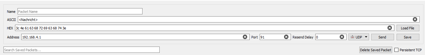
The Packet Sender menu looks like:
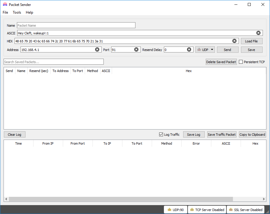
The Packet Sender Program
Under „File“ one finds „Settings“, where one has to configure the following:
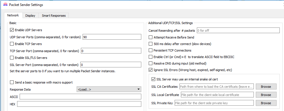
Packet Sender Settings (1)
Packet Sender Settings (2)
In TWedge the following devices have to be configured:
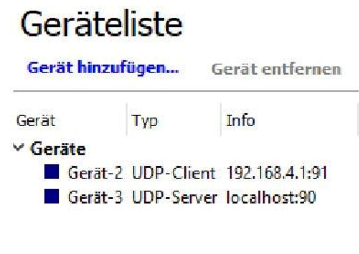
Twedge Devices
Substantially TWedge is a single Client, but in the program sending and receiving is separated. The program receives as Gerät 2 (UDP Client) and sends as Gerät 3 (UDP Server). Received data can be transferred to an Excel sheet and cell contents from the Excel sheet can be sent by TWedge to another Client or the Server.
Original sending and receiving:
Sending and receiving are supposed to be realized via the Serial Monitor of the Arduino, which we choose to have a baudrate of 19200. All messages, sent and received are terminated by CR and NL, so that the length is messagelength + 2. To send a message is announced by the following AT command:
AT+CIPSEND=<Id>,<messagelength+2>
where Id is the receivers Id as mentioned above. The ESP8266 answers with a prompt: „>“ and one can input the message. On the receivers side appears the following:
+IPD, <Id>,<length>:<message>
where Id is here the senders Id and length is the length of message.
Separation of At commands and sending and receiving
The separation of At commands sending and receiving to/from outside can be realized by the principle, that AT commands are sent solely by the Arduino sketch, and what appears on the Serial Monitor or is sent by it are pure messages. For the message a certain structure is chosen, to be aware about the final receivers Id (frId) or the original senders Id (osId), just what is of interest in the network. To this end the message consists of a net message Msg and a single Id. Both informations are separated by a colon (:).
message = <Msg> : <Id >
example: 170pv:1
When a Client sends, Id is the frId, and when it receives, it is the osId. For the Server holds the opposite.
The Server can get all information from the original receiving, which can only come from another Client:
+IPD, <osId>,<length>:<Msg>:<frId>
If he is not the receiver by himself, he passes the message to the Client with the frId removed and replaced by the osId, in the form:
message = <Msg>:<osId>
since for the final receiver is solely the original senders identity (osId) of interest.
| location | sending | receiving |
| Server | osId | frId |
| Client | frId | osId |
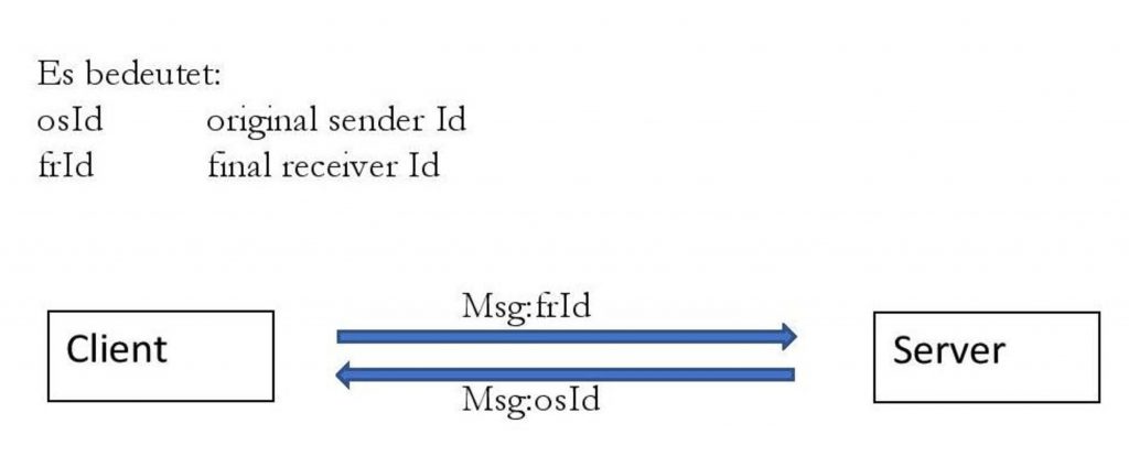
Message Structure
When via the respective Serial Monitor a message is entered without adding an Id, it is executed on place. Messages, which stem from other places of the network, have the form: +IPD, <Id>,<length>:<message>, thats why the string “+IPD,“ is used to distinguish messages from outside from answers of the ESP.
It may seem complicated, this adding of the respective Id, either osId or frId, but enables to handle only one Id for each event. Each participant of the network can send to every other participant and even to himself. Receiving a message, the recipient is aware that it was his address, where the message had to be passed. The only question, from where it is, he can see from the osId. Only the Server needs both informations, and can get it from the receivings.
If for example Client 1 wants to send to Client 2 the net message Msg = 123pv, he sends to the Server:
<Msg>:<frId> = 123pv:2
after handling by the Server at Client 2 arrives:
<Msg>:<osId> = 123pv:1.
The programs structure
The AT commands for configuring the ESP moduls are given in the Setup and are partially executed in subroutines (ConfigESP, ConfigWifi, StartCon and others), whereas the above mentioned IP addresses are defined and the participants of the network define themselfes as Server or Client (station).
In the Loop a hierarchy is defined with if else statements, priorizing receivings, that arrive via ESP, secondly it is looked after news from the Serial Monitor, and only in cases, where both are quiet, it deals with its own tasks.
Receivings via ESP
A receiving from the ESP can be a self generated answer (ESPsga). This is supposed in the beginning of each receiving from the ESP (Flag: ESPsga = true). Only if the sequence “+IPD,” is found, the ESPsga is set false. Since it is an alternative, the receiving is a message from outside. Now follows the parsing of the receiving. In the case of the Server the message might be to send further to the final receiver, by sending it to him while replacing the final receivers Id (frId) by the original senders Id (osId).
To this end the subroutine WiFiSend is used.
Sending via the Serial Monitor
Messages as well can be sent from each respective Serial Monitor and received messages are printed out there. The Baudrate is 19200 and CR and LF are to be set active.
Start using
The three NanoESP (Pretzelboards) have to be connected to three USB Ports and the Arduino IDE has to be started threefold. In “tools” select the “Arduino Nano” and as processor “ATMega328P” and select the respective COM Port. When the sketches for Server and Clients are uploaded, after some seconds at the Clients both blue LEDs should lid. Test sending and receiving data with the Serial Monitors.
On the Laptop the network NanoESP appears:
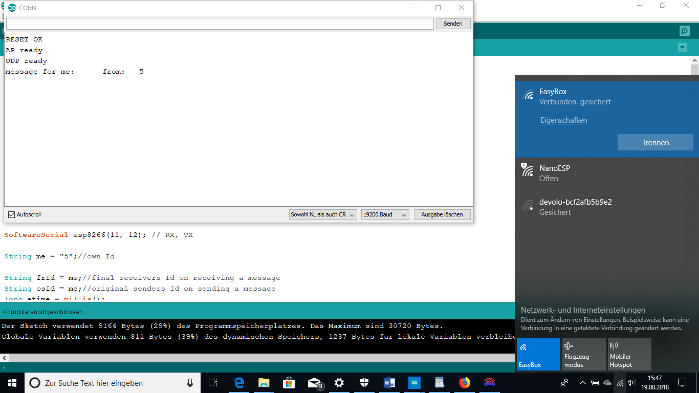
Das NanoESP Netzwerk
One should connect with this network, but note, that one has no Internet anymore, as long as one is connected with the Y network. The Firewall has to be deactivated:
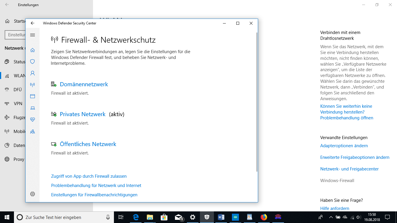
Firewall deaktivieren
Afterwards one can send from each Serial Monitor to another network participant messages and receive from others messages.
For example:
<message>:<frId> as example: a letter from me:0
(this message goes to the Laptop and either Packet Sender or TWedge).
We wish you fun with your WiFi UDP Y network and hope, that our work will help you further.
Dr. Christian Rempel & Laurin Kettner
Zeuthen im August 2018
Refer to AT commands: https://room-15.github.io/blog/2015/03/26/esp8266-at-command-reference/
Download: Ernteroboter_Programme